SenseCAP M1 Raspberry Pi Shield: Pinout and LoRaWAN Reuse
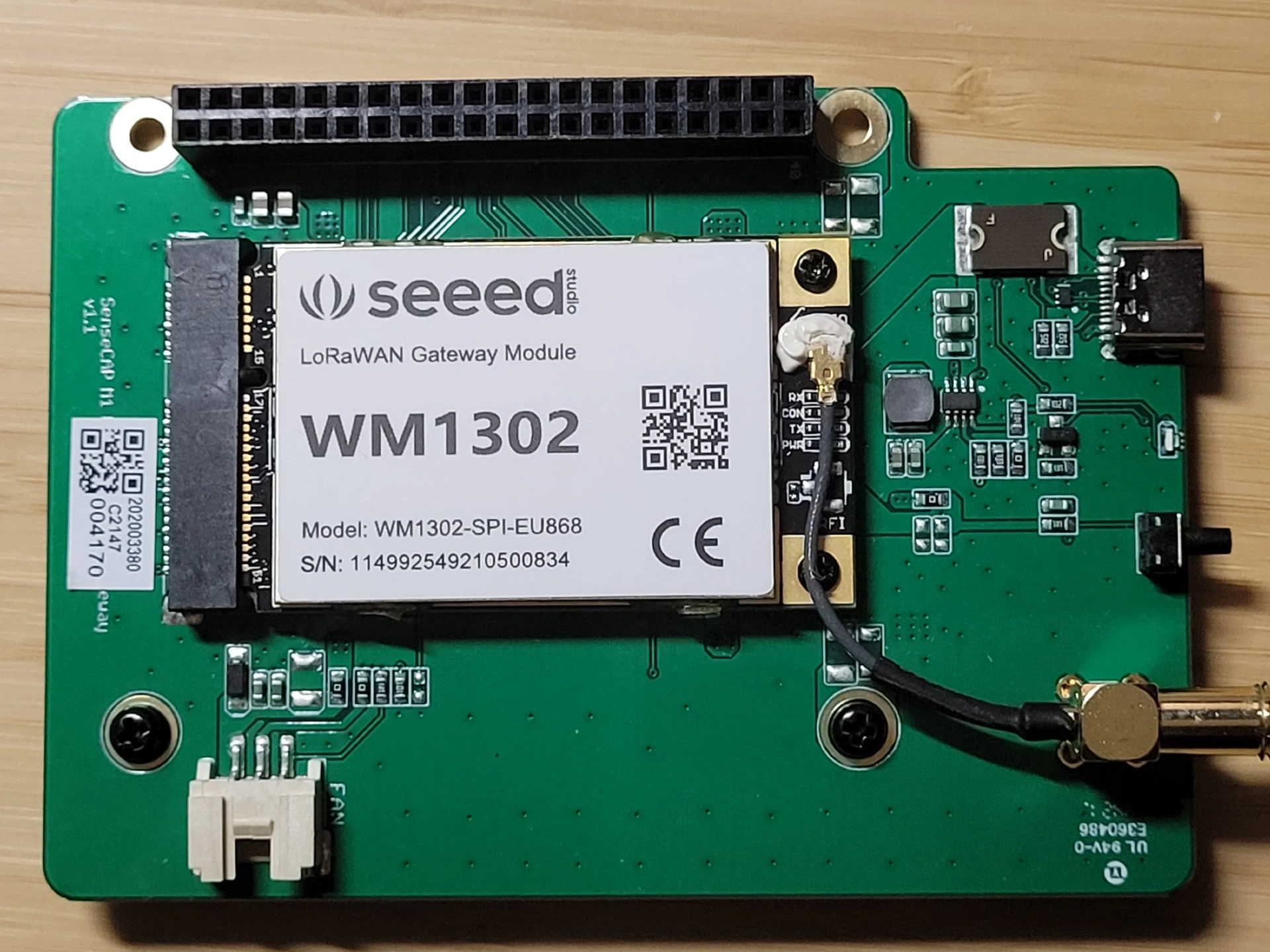
Table of Contents
The SenseCAP M1 shield is useful LoRaWAN gateway hardware, but its wiring deserves more scrutiny than a generic Raspberry Pi HAT tutorial provides. This guide expands Clockwork Bird’s 2023 investigation with manufacturer documentation, upstream driver inspection, and current GPIO guidance. You will identify the hardware, separate established facts from incomplete pinout evidence, and produce a repeatable bring-up record.
Scope: This is a documentation-based hardware guide. The commands and board mappings have not been tested on a physical M1 for this article.
Главные выводы
- Identify both boards: The M1 carrier and its removable concentrator have separate model and revision information.
- Audit reset scripts: CoreCell defaults conflict with signals in the published M1 pinout.
- Check the OS interfaces: SPI device files, GPIO numbering, and GPIO tool versions answer different questions.
- Preserve secure-element provisioning: Reading device information differs from configuring or generating keys.
- Prove the whole path: A detected concentrator does not establish successful sensor delivery.
Перед началом
Difficulty: intermediate. Budget roughly one to two hours for inventory, OS preparation, and documentation checks. Electrical verification, driver adaptation, and network-server deployment add separate work, especially with an unfamiliar board revision.
| Item | Purpose |
|---|---|
| M1 shield and concentrator | Read the carrier revision and the complete module label |
| Raspberry Pi 4 | Start with the host used in the original M1 design |
| Spare microSD card | Prepare a separate OS while preserving the original installation |
| Correct supply and antenna | Match the assembled hardware and the module’s RF band |
| SSH or local console | Record diagnostics and edit configuration |
| LoRaWAN sensor and server | Verify actual application delivery after hardware bring-up |
| Meter and hardware experience | Resolve undocumented connections before driving them |
Photograph both sides of your unpowered assembly before removing anything. Record connector orientation, screws, spacers, and antenna routing. Keep the original card and configuration available until the replacement installation passes your acceptance checks.
Identify the Three Layers
The complete M1, its carrier shield, and its concentrator are different components. Seeed documents the assembled hotspot as a Raspberry Pi 4 with either a WM1302/SX1302 or WM1303/SX1303 concentrator. A listing titled “SenseCAP M1 shield” does not establish which of those parts accompanies the carrier. Seeed Studio’s M1 overview
The carrier routes power and peripheral signals between the Pi and module. The concentrator handles radio reception and transmission. A packet forwarder runs on the host and exchanges received radio packets and scheduled downlinks with a server. Semtech’s SX1302 HAL overview
For a practical example, a shelf-temperature sensor sends an uplink over radio. The concentrator receives it, the host forwards it, and the network/application services process it. A successful Linux boot proves only the host portion of this chain.
Clockwork Bird’s photograph shows an M1 v1.1 carrier with a module explicitly labeled WM1302-SPI-EU868. Use the photograph to locate the labels on your own hardware. Its serial numbers identify the photographed equipment, not configuration values for another gateway.
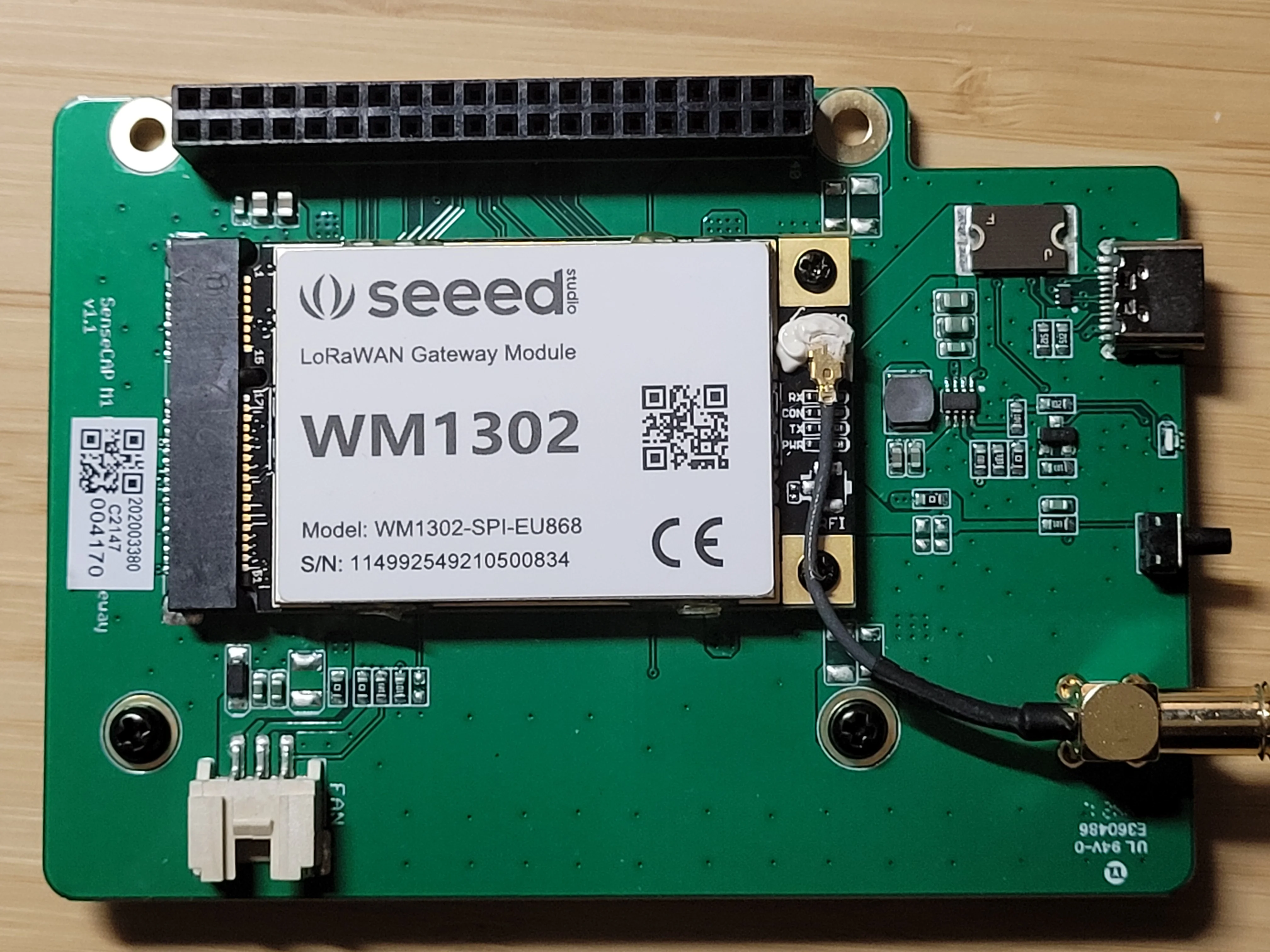
M1 v1.1 hardware photographed by Clockwork Bird, also used for this article’s cover · Clockwork Bird, 2023-05-03
Power and Radio Connections
Treat the M1 USB-C connector as a power input. The manufacturer specifies DC 5 V, 3 A for the complete gateway and identifies USB-C as its power-supply interface. Calling it a charging port suggests a battery function absent from those specifications. SenseCAP M1 specifications
The vendor block diagram separates the 5 V supply from the module’s regulated 3.3 V rail. This distinction matters during troubleshooting: a running Pi and an unpowered concentrator are separate possibilities. Do not inject 5 V into a signal pin or assume two power inputs are isolated from each other.
SPI and USB module variants require different host connections. Seeed’s WM1302 documentation describes direct SPI access for its SPI model and an STM32L4 USB bridge for its USB model. The mini-PCIe shape describes the module’s form factor, while the documented electrical interfaces are SPI or USB. A matching laptop socket is insufficient evidence of compatibility. Seeed’s WM1302 documentation
Before powering the assembly, seat the module with power disconnected and attach a suitable antenna. Match the RF hardware, antenna, and intended network plan. Changing a configuration filename does not replace the module’s RF components, and the M1 power socket does not prove support for a USB concentrator variant.
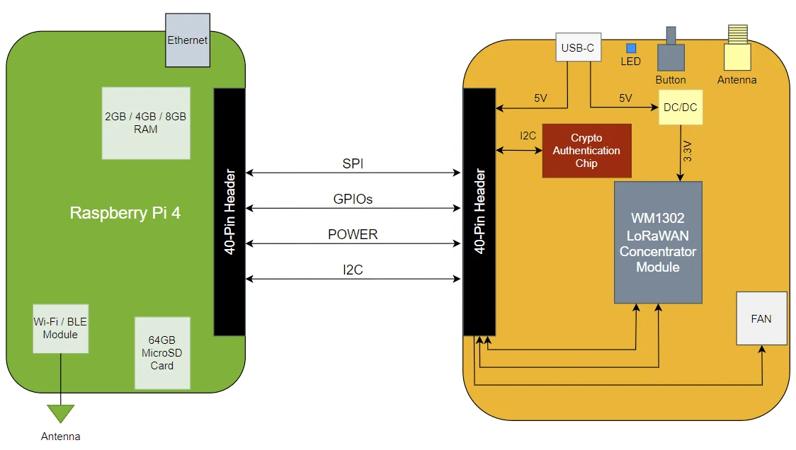
SenseCAP manufacturer diagram reproduced in Clockwork Bird’s original article, showing the WM1302 design · Seeed Studio / SenseCAP, via Clockwork Bird
Read the Pinout Carefully
Use BCM GPIO numbers and physical header numbers as separate columns in your notes. For example, BCM GPIO17 sits at physical pin 11 on the Pi header. The module edge connector introduces a third numbering system, so its reset pin number is not a Raspberry Pi GPIO number.
The table below transcribes the connections in Clockwork Bird’s annotated header image. It is a community reference, not a complete manufacturer-issued schematic or a measurement of every M1 revision. The drawing also uses SX1262 labels, while the generic Semtech reset script uses SX1261 names.
| Signal in the drawing | BCM / physical pin | Interpretation |
|---|---|---|
| I2C SDA / SCL | GPIO2 / 3, GPIO3 / 5 | Shared management bus |
| SX1302 reset | GPIO17 / 11 | Concentrator reset candidate |
| User LED | GPIO22 / 15 | M1 annotation |
| SPI MOSI / MISO | GPIO10 / 19, GPIO9 / 21 | SPI data signals |
| SPI clock | GPIO11 / 23 | SPI clock signal |
| SX1302 chip select | GPIO8 / 24 | SPI0 CE0 |
| SX1262 reset | GPIO5 / 29 | Auxiliary radio reset candidate |
| SX1262 chip select | GPIO6 / 31 | GPIO6, distinct from SPI0 CE1 |
| SX1262 BUSY | GPIO18 / 12 | Auxiliary radio status output |
| SX1262 IO1 / IO2 | GPIO23 / 16, GPIO24 / 18 | Auxiliary signals, verify before use |
The crossed-out GPS/UART annotations do not establish a GPS-equipped M1. Leave GPS-specific setup out of your configuration unless your actual hardware provides it. The published diagram also leaves the user button and fan control unresolved. Clockwork Bird’s pinout investigation
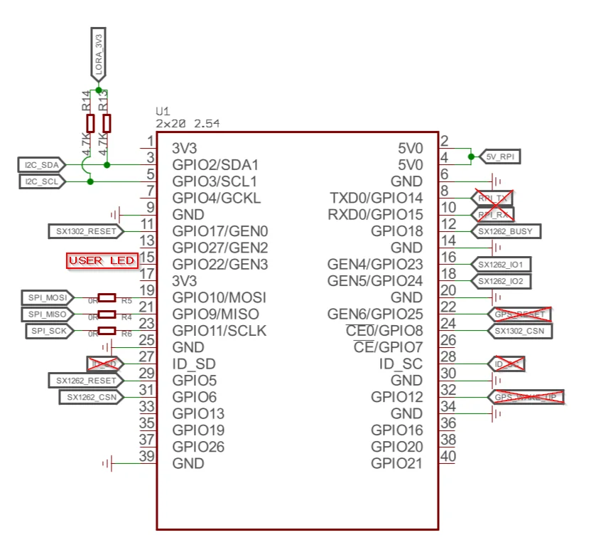
Community-annotated reference with unresolved board-revision coverage, not a complete M1 schematic · Clockwork Bird, 2023-05-03
Resolve Reset-Script Conflicts
A reset script selects electrical outputs, not merely software preferences. Semtech’s upstream reset_lgw.sh targets its CoreCell reference design. Its defaults include GPIO23 for concentrator reset, GPIO18 for power enable, GPIO22 for auxiliary reset, and GPIO13 for an AD5338R reset.
Semtech reset-script source
Seeed’s older setup instructions change the two reset assignments to GPIO17 and GPIO5 but retain the other reference-design entries. Compare those values with the annotated M1 image before following the example. Seeed WM1302 setup instructions
| Assignment | Conflicting evidence | Required decision |
|---|---|---|
| GPIO22 as auxiliary reset | M1 image labels it as the user LED | Remove this assumption before enabling the LED |
| GPIO18 as power enable | M1 image labels it as auxiliary BUSY | Verify the net and direction before driving it |
| GPIO13 as DAC reset | Generic script names a different reference design | Establish whether the circuit exists |
| Auxiliary SPI device | M1 image selects GPIO6 rather than CE1 | Confirm chip-select routing and driver support |
Inference: If GPIO18 connects to an auxiliary radio output as drawn, configuring the Pi end as an output creates a risk of electrical contention. The disagreement establishes a verification requirement, not proof of damage or proof of one universal M1 wiring map.
With all power disconnected, trace accessible connections between the header and module connector. Record the board revision and both endpoints. A continuity result establishes connectivity, while the component documentation establishes signal direction and electrical limits.
Use the manufacturer’s module diagram below to avoid mixing edge-connector pins with Pi header pins. The auxiliary-radio labels describe the published module reference and do not establish identical silicon or supported features across every module revision. Seeed WM1302 module pinout
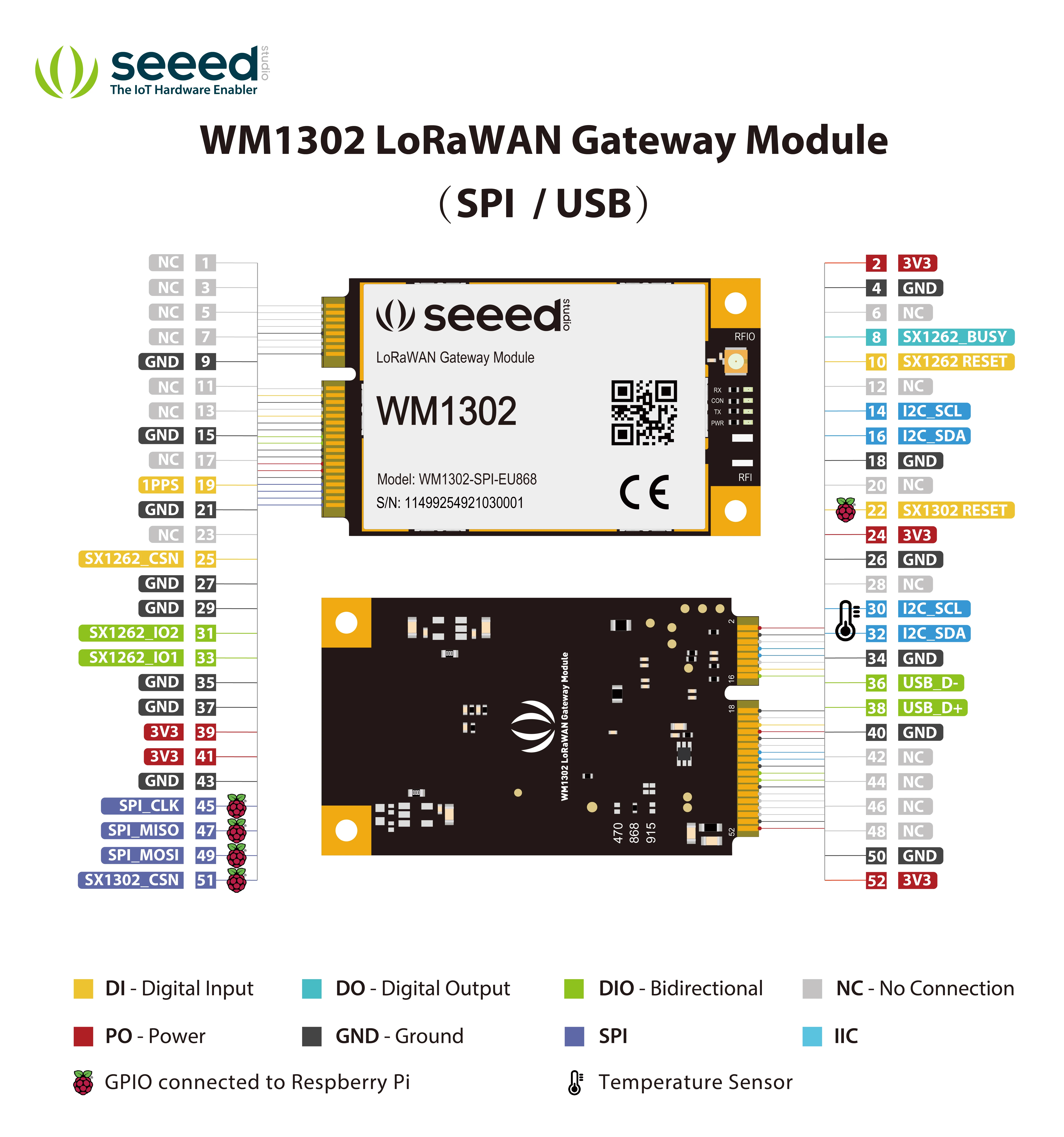
Module edge-connector numbering differs from Raspberry Pi header numbering · Seeed Studio, WM1302-doc
Prepare Raspberry Pi OS
Record the host environment on your spare installation:
cat /etc/os-release
uname -r
tr -d '\0' < /proc/device-tree/model
The OS release, kernel, and Pi model form the starting point for reproducibility. Record them before comparing your results with an older tutorial.
Install inspection and build tools:
sudo apt update
sudo apt install git build-essential i2c-tools gpiod
sudo raspi-config
In Interface Options, enable SPI and I2C, then reboot. SPI serves the concentrator path, while I2C supports the management devices discussed below. Avoid importing unrelated GPS serial-port changes from another HAT tutorial.
Inspect the exposed interfaces:
ls -l /dev/spidev* /dev/i2c-*
i2cdetect -l
gpiodetect
gpioinfo
gpioset --version
These commands list device nodes, adapters, GPIO controllers, line information, and the installed GPIO tool version. i2cdetect -l lists adapters without scanning device addresses. A /dev/spidev0.0 file establishes an exposed SPI interface, not communication with a working concentrator.
i2c-tools manual
,
Raspberry Pi GPIO guidance
Account for GPIO Versions
Do not copy global GPIO numbers from another machine. Old scripts write through /sys/class/gpio, an interface the kernel documents as deprecated. New userspace integrations should use the GPIO character-device interface, with the correct controller and line offset.
Linux GPIO documentation
Also inspect gpioset --help before adapting a script. Version 1 and version 2 differ in syntax and process behavior. The current tool holds requested lines by default, and its portable contract does not guarantee their state after process exit.
libgpiod gpioset documentation
Raspberry Pi documents an output-persistence behavior in its kernel, with options to change it. Record the actual kernel configuration instead of assuming every Linux system behaves identically. Neither updated numbering nor a newer GPIO tool resolves an incorrect electrical mapping. Raspberry Pi GPIO usage guide
Test the User LED
After verifying GPIO22 belongs to the LED and removing conflicting GPIO consumers, edit the boot configuration:
sudoedit /boot/firmware/config.txt
Modern Raspberry Pi OS mounts the boot configuration at /boot/firmware/config.txt. Older images use /boot/config.txt, the path in the 2023 article. Back up the active file before editing it.
Raspberry Pi config.txt documentation
Add the LED overlay under a section applying to your Pi, such as [all]:
dtoverlay=gpio-led,gpio=22,label=lorawan,trigger=heartbeat
The gpio parameter uses BCM numbering. label names the Linux LED device, and trigger=heartbeat assigns the kernel heartbeat trigger. Clockwork Bird reports this assignment for the M1, and Raspberry Pi’s overlay reference documents these parameters.
Original LED observation
,
gpio-led overlay reference
After reboot, inspect the registered LED:
ls -l /sys/class/leds/
cat /sys/class/leds/lorawan/trigger
The expected result is a lorawan LED entry with heartbeat selected in brackets. A blinking LED demonstrates this GPIO/driver path. It does not report successful LoRaWAN registration, radio reception, or Helium status.
Investigate I2C Devices
An I2C address is a clue, not a device identity. Clockwork Bird observed responses at 0x60 and 0x39, then read ATECC608 information through the crypto library. The temperature-sensor identification remained tentative in the original article.
Start with the adapter listing from the previous section. Broad i2cdetect scans send probing transactions rather than passively observing traffic, and the upstream manual warns about disruption. Avoid routine scans of a running gateway or unknown attached devices.
i2c-tools probing behavior
| Observation | Supported conclusion | Unresolved question |
|---|---|---|
Response at 0x60 |
Something acknowledged the probe | Is it the expected secure element? |
Response at 0x39 |
Something acknowledged the probe | Which component and revision responded? |
UU in a scan |
A driver owns the address and probing was skipped | Which driver has ownership? |
| No response | The probe received no acknowledgement | Power, bus, ownership, or device protocol? |
A Stronger Temperature-Sensor Lead
STTS751 is a source-supported candidate for 0x39. Semtech’s temperature-driver header explicitly associates 0x39 with STTS751-0DP3F. This strengthens the original hypothesis without identifying every board populated at this address.
Semtech STTS751 driver header
After identifying a compatible component and ensuring no other process owns it, these commands read its identification registers:
sudo i2cget 1 0x39 0xfd b
sudo i2cget 1 0x39 0xfe b
Here 1 selects the verified bus, 0x39 selects the device, and b requests an SMBus byte-data read. For an STTS751-0, the documented product ID at 0xFD is 0x00, and the manufacturer ID at 0xFE is 0x53. These transactions select register addresses but do not program configuration values.
STTS751 datasheet, register map and identification registers
Compare the readings with the chip marking and documentation. A matching pair adds evidence for identification, while an error calls for checking the bus and ownership before changing hardware configuration. The sensor measures its local temperature, which is a different measurement from the Pi’s CPU temperature.
Inspect the Secure Element
The ATECC608 is a separate authentication component. Treat its configuration, serial number, public key, and protected key material as distinct concepts. A readable public key does not reveal the corresponding private key.
Microchip’s CryptoAuthLib provides the device interface. Its cryptoauthtools repository contains examples built around the library. Prepare the native library and Python bindings for your target system using those projects’ instructions before invoking an example. Installing an unrelated Python package or copying one script alone does not establish an operational I2C backend. Microchip CryptoAuthLib , Microchip cryptoauthtools
From a prepared cryptoauthtools/python/examples directory, the original article’s inspection command is:
sudo python3 info.py -i i2c
The -i i2c argument selects the interface. With a virtual environment, use its explicit Python interpreter and ensure it locates the matching native library. sudo python3 selects the system interpreter in many installations, which explains some module-import failures.
The reviewed info.py reads revision information, the serial number, configuration, and lock status. For a locked data zone, it attempts to retrieve the public key from slot 0. It does not run the example provisioning sequence. A slot-0 public-key failure alone does not establish a broken device.
Microchip info.py source
| Output or operation | Meaning |
|---|---|
| Configuration locked | Configuration restrictions are in force |
| Data zone locked | Interpret access through the configured slot policies |
| Public key displayed | Public information was retrieved, not a private-key export |
config.py execution |
Provisioning example with configuration, locking, and key-generation operations |
Do not run config.py to repair an inspection error. Its source includes configuration writes, zone-locking calls, and key generation. Its default key-generation path also matters on an already configured device.
Microchip config.py source
Microchip’s documented provisioning profiles illustrate why a locked data zone does not mean every slot has identical access permissions. Those profiles do not establish the M1’s exact configuration. Preserve the device’s existing configuration and consult the matching part documentation before planning any reuse involving keys. Microchip memory and slot-access policies
Handle Fan and Button Unknowns
A three-pin fan socket does not establish its voltage, polarity, or control method. Photograph its pin numbering and read the fan label. Resolve power and control connections before attaching a replacement or choosing a GPIO overlay.
Likewise, the original investigation leaves the button’s GPIO unknown. Search for a driver or configuration tied to your board revision, then verify connectivity with power disconnected. Do not assign every apparently unused GPIO as an output to find the button.
| Peripheral | Evidence to collect | Acceptance condition |
|---|---|---|
| Fan power | Fan rating, connector ground and supply | Measured supply matches the fan specification |
| Fan control | Driver/configuration or traced control circuit | Defined behavior at startup and elevated temperature |
| User button | Contact wiring, GPIO mapping, input polarity | One intentional press produces the expected event |
A fresh OS installation does not automatically reproduce the original appliance’s cooling policy. During your first sustained test, observe fan operation and temperatures together. Preserve the enclosure’s airflow path and stop the test if the assembly loses its required cooling.
Choose a Gateway Stack
Separate board support from server protocol. A compatible LoRaWAN server does not fix an incorrect reset routine or RF calibration. First choose software with support for the concentrator, carrier wiring, OS, and regional configuration.
| Software path | Useful role | Check before deployment |
|---|---|---|
| Semtech SX1302 HAL | Source-level bring-up and diagnostic tools | Board reset routine and module configuration |
| LoRa Basics Station | Authenticated gateway connection to a server | Working board integration and server credentials |
| ChirpStack Concentratord | Dedicated concentrator service | Supported model, calibration, and GPIO mapping |
ChirpStack lists a seeed_wm1302 SPI model. This is evidence of module support, not a promise of a complete M1 image or support for every M1 revision. Avoid treating the separate SenseCAP M2 installation instructions as M1 firmware instructions.
ChirpStack hardware support
,
ChirpStack’s Seeed installation target
For The Things Stack, its documentation recommends LoRa Basics Station over the legacy Semtech UDP forwarder. Station provides TLS and token-based authentication alongside centralized configuration features. Existing UDP examples are useful for understanding packet forwarding, but their server-address settings do not provide those protections. The Things Stack UDP guidance , LoRa Basics Station documentation
Prepare the Upstream Tools
Build on the target Pi in a new working directory:
git clone https://github.com/Lora-net/sx1302_hal.git
cd sx1302_hal
git rev-parse HEAD
make
Save the commit identifier with your build output. A completed build establishes compiler compatibility, while the radio still requires the verified reset implementation and correct configuration. Semtech’s documentation explains the role of its HAL and helper programs. SX1302 HAL build and tool documentation
Review the reset file before running hardware-access tools:
sed -n '1,180p' tools/reset_lgw.sh
Do not copy this file into the runtime directory unchanged. Semtech documents automatic reset-script use by its hardware-access programs, including tools used during identification. Your review must cover every assigned pin, signal direction, GPIO API, and startup/shutdown state.
After completing board verification, use the selected stack’s instructions to read the concentrator EUI and register the gateway. Preserve the module’s calibration and RF settings when adding the server configuration. In Semtech UDP configuration, gateway_ID represents the EUI, while The Things Stack’s console Gateway ID is its human-readable registration identifier.
The Things Stack gateway configuration
Prove Sensor Delivery
Use staged evidence to locate the first failing layer. A gateway marked online establishes a server connection. Your acceptance test also needs a known sensor, matching frequency plan, and a decoded application payload.
The following sequence is a proposed test plan, not measured M1 results:
| Checkpoint | Evidence to save | Meaning |
|---|---|---|
| Host ready | OS, kernel, power and interface inventory | Linux preparation completed |
| Concentrator responds | EUI and successful initialization log | Host-to-concentrator communication works |
| Radio receives | Expected sensor packet and reception metadata | The configured receive path works |
| Server accepts | Gateway event associated with the sensor | Forwarding and server routing work |
| Application decodes | Expected measurement and timestamp | The application path works |
| Reboot recovery | Same checks after restart | Startup configuration is reproducible |
For an OTAA sensor, also confirm the activation exchange and subsequent uplink. OTAA means over-the-air activation, the join procedure used to establish a session. A received join request alone does not establish a successful join or downlink path. The Things Stack activation documentation
Worked diagnosis: Suppose the gateway connects to its server and reports its EUI, but your sensor never appears. Prioritize the sensor’s transmit configuration, selected receive channels, antenna path, and radio logs. Reprogramming the ATECC608 would not address the missing evidence in this scenario.
Second diagnosis: Suppose a sensor packet appears locally but never reaches the application. Correlate the packet time with gateway and server events, then inspect routing, device registration, and decoding. An RF packet in a log is insufficient evidence for blaming the payload decoder until the server accepts the event.
Troubleshooting by Symptom
| Symptom | Check first | Next action |
|---|---|---|
| No SPI device file | Active boot configuration and interface settings | Enable the intended interface and reboot |
| SPI exists, radio fails | Power, seating, reset sequence and chip select | Verify the electrical path before server changes |
| GPIO export error | Legacy sysfs assumptions and installed kernel | Use a reviewed implementation for the GPIO API |
| GPIO already in use | Consumer shown by gpioinfo |
Resolve ownership before retrying |
| LED fails after setup | Overlay application and GPIO22 conflicts | Inspect registered LED devices and reset script |
| I2C device absent | Bus number, power and existing ownership | Investigate without repeated broad scans |
| Crypto library import fails | Interpreter, bindings and native library path | Fix the software environment |
| Public-key read fails | Slot policy and earlier successful reads | Review configuration without provisioning |
| Fan does not run | Verified supply and cooling-control implementation | Restore correct cooling before sustained tests |
| Uplinks arrive, join fails | Downlink path and regional/device settings | Trace the join response and receive windows |
Treat each correction as one experiment. Save the previous configuration, change one variable, repeat the same check, and record whether the expected evidence appeared.
Create Your Hardware Record
Use this template to turn the investigation into a reproducible handover:
Carrier revision and photographs:
Concentrator model, interface and RF band:
Host model / OS / kernel / GPIO tool version:
Supply / antenna / cooling arrangement:
Verified pin mapping and evidence:
Unresolved nets and excluded features:
Software repository and commit:
Reset implementation and GPIO ownership:
Gateway EUI / server / frequency plan:
Sensor activation and decoded uplink evidence:
Reboot recovery result:
Original-card location and rollback procedure:
Decision exercise: You have an inexpensive bare carrier with no module label, and a more expensive assembly with readable labels and documented operation. Decide which fits your project after adding the missing Pi, concentrator, antenna, supply, and verification time to the comparison. The stronger choice follows the total cost and evidence required for your intended service, rather than the carrier’s advertised price alone.
Expected reasoning: A learning project tolerates unresolved wiring if you have measurement tools and time. A gateway supporting operational sensors needs repeatable startup, cooling, software support, and demonstrated delivery. Record which unresolved condition would stop your deployment.
Следующие шаги
Start by completing the hardware record and resolving the reset-script discrepancies. Then bring up one known sensor and save evidence through application decoding before adding more devices.
Acceptance record: save the board revision, module label, radio band, supply measurement, active SPI device, GPIO line names, reset sequence, concentrator log, server connection, and one decoded uplink. Mark every value as observed, documented, or still assumed. Do not treat a successful process start as proof of RF performance or application delivery.
If your goal is mesh messaging, first compare the protocol roles in our Meshtastic, MeshCore, and Reticulum guide . Sharing LoRa radio technology does not establish firmware compatibility. Consult MeshtasticD’s supported-hardware documentation for a messaging deployment instead of treating this LoRaWAN procedure as a Meshtastic conversion.
Sources and Image Credits
Research checked September 12, 2026. Undated documentation and repository links refer to the versions reviewed for this article. Local figures retain their original labels and credited provenance.
| Publisher | Source and date |
|---|---|
| Clockwork Bird | SenseCAP M1 Raspberry Pi Shield , 2023-05-03. Board photograph, annotated header, and reproduced manufacturer block diagram |
| Seeed Studio / SenseCAP | M1 overview and specifications , undated. Original block-diagram attribution |
| Seeed Studio | WM1302 documentation and module pinout , repository |
| Semtech | SX1302/SX1303 HAL , including linked reset-script and temperature-driver source |
| Raspberry Pi | Boot configuration , GPIO usage guide , and overlay reference |
| Linux / libgpiod | Deprecated GPIO sysfs interface and gpioset manual , latter dated August 2026 |
| i2c-tools | i2cdetect manual , v4.3 source |
| STMicroelectronics | STTS751 datasheet , revision 7 |
| Microchip | CryptoAuthLib , cryptoauthtools , and slot-access policy documentation |
| ChirpStack | Concentratord hardware support and Seeed installation target |
| The Things Industries | UDP forwarder , LoRa Basics Station , and device activation |
| Meshtastic | MeshtasticD documentation , undated |